IBSTOCK COLLIERY (SK 416111)
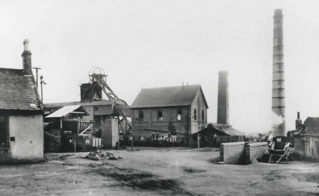
Ibstock Colliery
Copyright © NMRS Records: Geoff Hayes Collection
Ibstock Colliery was one of the early sinkings into the concealed part of the Leicestershire coalfield (Eastern Basin). One William Thirlby, a farmer and lace manufacturer of Ibstock Grange, sank shafts in 1825 and succeeded in reaching workable coal seams. Thirlby had grossly underestimated the costs of sinking a new colliery and Ibstock Colliery had a very shaky start indeed. By the early 1830’s however, the colliery was working the Upper and Lower Main coal seams. A branch line was also built to connect with the Leicester & Swannington Railway and this branch was opened in 1832.
In the latter part of the 19th century, but before 1890, the colliery comprised three shafts. Two shafts were sunk 17 yards apart, one being the coal winding shaft and the other the pumping shaft. These were both 8 feet diameter. Some 130 yards away was the upcast shaft, also 8 feet diameter.
The year 1890 saw the sinking of a fourth shaft, 14 feet diameter, near to the upcast shaft. The new shaft was downcast and coal winding and together with the existing upcast shaft was known as the No.2 Plant. The older winding and pumping shafts together became the No.1 Plant. The existing upcast shaft served both mines.
The old No.1 downcast shaft intersected the (Upper) Main Coal at approximately 81 yards from the surface and the Lower Main or Roaster seam at approximately 137 yards. The total depth sunk was just under 170 yards.
Winding – The winding engine at the No.1 Plant was a twin cylinder horizontal, 20in. x 54in., fitted with ordinary slide valves for steam distribution. The winding drum was slightly conical, 10 feet diameter at the outer edges increasing to 10ft. 9in. at the centre. A brake path was fitted at one side of the drum, to which was applied an under-strap brake operated by a foot lever mechanism. Two double deck cages were wound in the shaft, each carrying two 13 cwt. capacity tubs, one on each deck. Winding ropes were of crucible steel I¼ inches diameter. Each cage was guided by two pitch pine conductors. The winding level was at 144 yards from the surface.
Underground Haulage (No.1 Plant) – The haulage engine was a single cylinder horizontal, 16in. x 24in., geared 1 to 7 to the second motion shaft. A Clifton wheel 6 feet diameter was fitted on the second motion shaft and an endless wire rope made 3½ turns around this wheel, from where it passed down the downcast shaft to a Clifton wheel fitted on a vertical shaft near to the pit bottom. The endless rope made a number of turns around this Clifton wheel and after passing around a tension pulley returned up the pit shaft to the surface haulage engine. The tension pulley was mounted on a carriage held in position by weights. On the vertical shaft was a second Clifton wheel, 6 feet diameter, which was driven through a toothed clutch. This second Clifton wheel drove the main haulage endless rope. The main haulage roadway was approximately 1200 yards in length. The first section was a cross measure drift which was driven inbye from the winding level in the shaft on a rising gradient for some 400 yards where the Main Coal seam was intersected. The roadway then proceeded down dip to a pony level. From the pony level the working stalls were driven to the rise. The loaded tubs were brought down to the pony level by self-acting inclines or “jigs”. Ponies then hauled the tubs to the main haulage road where they were transferred to the endless rope haulage system. Smallman clips were used to attach the tubs in gangs of two to the haulage rope which ran under the tubs.
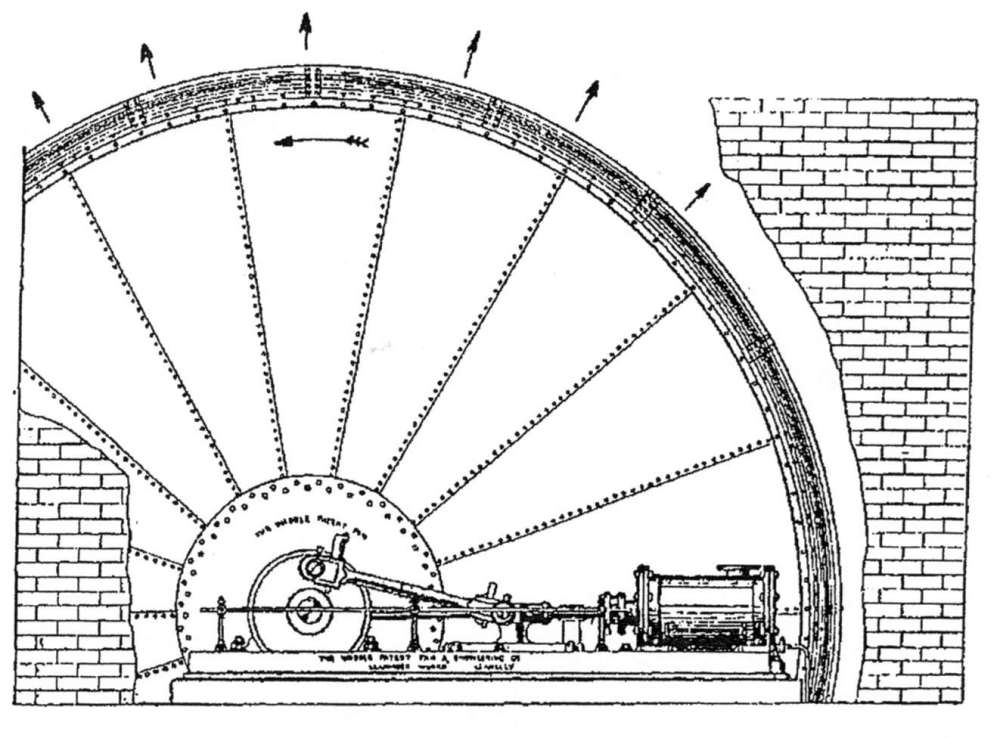
Waddle Patent mine ventilating fan with drive by a single cylinder horizontal steam engine as installed at Ibstock Colliery – Mechanical Engineering of Collieries.
Ventilation – A Waddle Patent fan was installed at the upcast shaft in 1894. The fan was 18 feet diameter over the blades and was fitted with an evasee rim. Running at 80rpm the fan circulated 50,000 cubic feet of air per minute against a mine resistance of 0.9 inches water gauge. A 16 inch single cylinder horizontal engine, coupled directly to the fan shaft provided motive power.
Pumping – The pumping shaft was sunk to a depth of 150 yards. A beam pumping engine was located at the top of the pumping shaft. This engine was reputedly made by Boulton & Watt at the Soho Works. The cylinder was 56in. bore by 4ft. 6in. stroke. The beam fulcrum was fixed to the front wall of the engine house and from the outdoor nose of the beam three lifts of bucket pumps were operated. Each lift was about 150 feet. The engine dealt with the total flow of water into the mine, which included the flow from abandoned old workings. Typical operation was for 12 hours per day at 4½ working strokes per minute. Information obtained locally indicates that this pumping engine remained at the colliery until closure in 1928.
Underground a 3-throw ram pump was situated at the end of the endless rope haulage system. Motive power for the pump was obtained from the vertical shaft of the return wheel of the endless haulage rope. Power was transmitted to the pump by gearing and by endless rope and pulleys. The pump was made by Messrs. Wootton of Coalville. The rams were 5in. diameter, single acting. Delivery of water was approximately 35 gallons per minute. Water was delivered through a 4 inch diameter cast iron pipe to the top of the cross-measure drift from where it gravitated to the pumping shaft sump.
To drain some old workings a syphon system was used to raise water to the top of the cross-measure drift and thence to the pumping shaft sump.
Boilers – Four Lancashire boilers were installed, constructed of steel and measuring 8 feet diameter by 30 feet long. One boiler was made by Marshall & Co. of Motherwell. At the time of compilation of the Colliery Guardian review in 1896, these four boilers would have been quite new. At this time also, there was a strong Scottish connection in both ownership and management.
There were also 4 egg-ended boilers installed, two of which were fitted with Meldrum’s forced draught furnaces.
[GH note – It seems improbable that the new Lancashire and the egg-ended boilers could be operated coupled together in parallel. Possibly the egg-enders were used to provide steam for the beam pumping engine.] Boiler feed was supplied by two live steam injectors made by Messrs Smith & Co. of Nottingham. A steam pump was also provided as a reserve. The chimney serving the boiler plant was 128 feet in height and 6 feet inside diameter.
Underground Working – The seam worked was the Main Coal and longwall working was in use. The working stalls were set out on the rise side of the pony level. The tubs were manhandles to and from the stalls to the self-acting inclines (jig roads) which lowered the full tubs to the pony level and brought up the empties. Naked lights were used by the miners throughout.
Coal preparation – The full tubs after removal from the cages passed over a weighbridge and then alongside railway wagons. Large coal was picked off the tubs by hand and placed in the wagons. Four sorts of coal were thus dealt with, these being two grades of house coal and two of steam coal. The partially empty tubs were then raised and the contents deposited on a jigging screen by a tippler.
The coal was graded into four sizes, cobbles, nuts, peas and slack. Cobbles and nuts were directed on to separate picking bands where they were cleaned by hand before dropping into separate railway wagons. The screening plant was driven by a steam engine.
No.2 Downcast Shaft (No.2 Plant)
The No.2 downcast shaft was sunk in 1890 and was 14 feet diameter and 150 yards in depth to a cross-measure drift.
Winding – The winding engine at this shaft was made by Messrs Inglis, Hossack & Co. of Airdrie. It was a twin cylinder horizontal with 24in. x 66in. cylinders fitted with piston valves for steam distribution. A parallel winding drum of cast-iron and 12 feet diameter by 6 feet wide was mounted on the crankshaft and had 3 sets of 8 cast-iron arms of T – section. The drum was lagged in elm, 5½ inches thick. A cast-iron brake path, 13 feet diameter was fitted to one side of the winding drum and was acted upon by a clasp brake operated by a foot lever. The brake segments or blocks were 8 feet long and lined with pieces of hemp rope to increase friction.
Two single deck cages were wound in the shaft each cage carrying two 10½ cwt. capacity tubs. Each cage was guided by 3 wire rope conductors the ropes being of locked coil pattern.
Underground Haulage – From the bottom of the downcast shaft a cross-measure drift was driven in a north-easterly direction for a distance of 150 yards and rising at 1 in 12. At this the Lower Main seam was intersected. The haulage road from this point was partially level and partially dipping to serve a “south level”. This level served the working places.
The haulage engine was placed near the upcast shaft, underground, and was a twin cylinder horizontal engine having cylinders 18in. x 36in. It exhausted into the upcast shaft. A second motion shaft was geared to the crankshaft in the ratio of 4 to 1 and a Clifton pulley’ was mounted on this second shaft. An endless haulage rope was passed around the pulley 4½ turns and this endless rope served the cross-measure drift and the haulage road to the south level. A tension pulley was incorporated in the run of the rope and at the termination of the haulage road at the south level a return pulley fitted on a vertical shaft was provided. On this vertical shaft and driven through a clutch, a 5ft. 6in. diameter Clifton pulley was fitted. An endless rope made 4½ turns around this pulley and this rope provided the haulage on the south level. The tubs were attached to the haulage ropes by means of screw clips.
Pumping – An underground pump was provided in the Lower Main seam. This was a single acting type with 2 – 5in. diameter rams and delivered into the beam engine pumping sump. It was made by Messrs. Wootton of Coalville. Power for the pump was probably provided by the main haulage rope through a pulley system.
Boilers – Two Lancashire boilers were located at the No.2 Downcast shaft. These were 8 feet diameter by 30 feet long and made in steel by Messrs. John Marshall & Co. of Motherwell. Working pressure was 80 psi., but they were actually made for 120 psi. Boiler feed was by live steam injectors, with one in service and one in reserve. The boilers were served by a square section chimney, 70 feet high and 4ft. 6in. square inside.
Lighting – Electric lighting was provided at both of the colliery sites. The system was direct current at 110 volts. A compound wound dynamo, made by Roper & Co. of Bradford, provided the current and had a rating of 70 amperes. The dynamo was powered by a 12½in x 26in. single cylinder horizontal engine. Lighting was provided at the screens and picking bands, in the workshops and the offices. An insulated copper cable was taken down No.2 downcast shaft inside a wrought iron pipe to provide lighting at the pit bottom and 80 yards of sidings.
Underground Working – At the time of the 1896 survey by the Colliery Guardian, the Lower Main seam was being worked from No.2 downcast shaft. Longwall working was the method of working used throughout.
Coal Preparation – A pit bank consisting of a wooden framework stood 24 ft above the rail level of the railway sidings. The screening plant comprised jigging screens and picking belts for grading and cleaning the coal. The equipment had been made by Messrs. Wootton of Coalville. The jigging screens and picking belts were driven by a 10in. x 24in. single cylinder steam engine.
No.1 Downcast Shaft
Summary of Shaft Section
| Seam | Thickness of Coal |
Depth from Surface | ||||
| Feet | Inches | Yards | Feet | Inches | ||
| Triassic measures | 60 | 0 | 0 | |||
| Coal – 1ft. 0in. | ||||||
| Cannel – 2ft. 9in. | 3 | 9 | 61 | 0 | 9 | |
| Coal | 10 | 62 | 1 | 8 | ||
| Cannel – 10in. | ||||||
| Coal – 3ft. 2in. | 4 | 0 | 67 | 1 | 4 | |
| Main Coal | 5 | 6 | 81 | 0 | 8 | |
| Little Coal | 1 | 6 | 81 | 3 | 2 | |
| Slate Coal | 4 | 6 | 89 | 1 | 0 | |
| Five Feet | 5 | 4 | 116 | 0 | 0 | |
| Seven Feet | 7 | 0 | 119 | 1 | 0 | |
| Four Feet | 3 | 7 | 133 | 1 | 6 | |
| Low Main (or Roaster) (excl. a thin coal left for roof and 6in. of clod) | 6 | 0 | 137 | 2 | 0 | |
| Coal | 1 | 2 | 151 | 2 | 2 | |
| Coal (at bottom of shaft) | 1 | 0 | 169 | 2 | 5 | |
Brickworks – A workable seam of fireclay was intersected by the pit shafts, and there were extensive clay deposits close to the colliery site. The brickworks produced firebricks, building bricks and sanitary pipes. In 1896 there were two brickmaking machines by Wootton of Coalville and several machines for pipe making.
The brickworks long outlasted the colliery and the name or brand Ibstock Bricks became nationally known.
COLLIERY CLOSURE – 1928
Copyright © NMRS Records: Geoff Hayes Collection
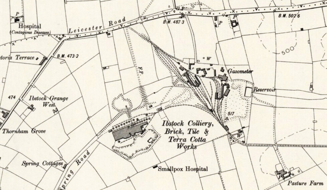
OS Map, Leicestershire XXIII.SE 1901
Reproduced by permission of the National Library of Scotland