SOUTH LEICESTER COLLIERY (SK 430118)
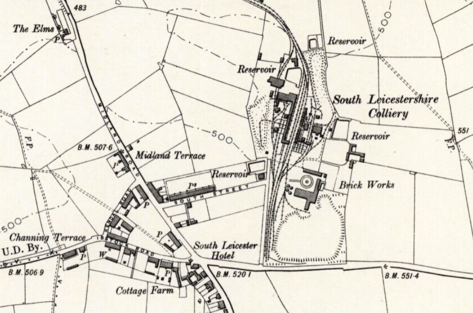
OS Map, Leicestershire XXIII.SE 1901
Reproduced by permission of the National Library of Scotland
The Colliery Guardian reported on this colliery in 1892 and 1896. The owners were the South Leicestershire Colliery Company Ltd, who at this time also owned the Snibston Collieries. The title of the Company and the colliery is a mystery as it is situated in North West Leicestershire.
Sinking of the colliery was commenced in January 1876 and comprised two shafts 60 yards apart. They were located near to Hugglescote station on the Shackerstone Junction – Coalville East – Loughborough railway line of the then London & North Western Railway. The Upper Main Seam was reached in November 1876 and the Lower Main Seam in January 1877.
Both shafts were 14 feet diameter, the downcast (No.2) shaft being sunk to 294 yards and the upcast (No.1) shaft was sunk to 282 yards. In No.2 shaft the Upper Main Seam was intersected at 214 yards, 6 inches and the Lower Main Seam at 272 yards, 1 foot 4 inches. At 59 yards 1 foot the Whitwick dolerite was encountered, this igneous intrusion having a thickness of 5 yards 1 foot 4 inches at this location. The Upper Main Coal was 5ft. 10ins. thick in the No.2 shaft and the Lower Main Coal 7ft. 2ins. The top 6ft. of the Lower Main was regarded as “Best Coal” and the bottom 1ft. 2in. as soft coal. Interspersed amongst some coals higher in the sequence were bands of fireclay which were not associated with any coal seam.
The downcast shaft was lined as follows, the upcast shaft being lined similarly:-
| 9 inch red brick from surface, puddled behind with clay: | 19 yards |
| Cast-iron tubbing in rings 2ft. Deep: | 71 yards |
| 9 inch red brick to bottom of shaft (downcast): | 204 yards |
| Total depth: | 294 yards |
Originally the Upper Main coal was wound in the downcast shaft from a depth of 239 yards, the workings being mainly to the rise from the shaft. North of the shafts a fault was present ranging north-west to south-east, with a downthrow of 99 feet to the north. To enable the Main Seam coal to be won on the downthrow side of the fault, the winding level was moved down to 272 yards in the shaft. From this new winding level a level drift was driven in stone to intersect the Main Seam on the downthrow side of the fault.
To reach the Lower Main Seam on the downthrow side of the fault, a stone drift dipping at 1 in 4 was driven from the 282 yard winding level in the upcast shaft until it intersected the Lower Main Seam on the down throw side of the fault.
Winding – The winding engine at the downcast shaft was made by Messrs. J.D. Leigh, Ellesmere Foundry, Patricroft. It was a twin cylinder horizontal engine having cylinders 30in. x 60in., fitted with Cornish valves for steam admission and exhaust. The winding drum was of cast-iron, slightly conical with a brake path on each side. A mechanical foot brake operated on the underside of the drum. Drum diameter at the outside edges was 14 feet, with the centre of the drum being slightly larger. The drum was constructed in three sections with 3 arms to each section.
Winding ropes were of plough steel, 4¼ inches in circumference. Three wire rope conductors were provided for each of the two cages, each rope being weighted 3 tons at the bottom. The arrangement of the conductors was a rope at the two outside corners of the cages and one central rope on the inside faces. The cages carried two 10½ cwt. capacity tubs, end to end on the single deck.
At the upcast shaft, the winding engine was a twin cylinder horizontal built by John Stead & Son of Cleckheaton. The cylinders were 36in. x 72in. fitted with Cornish valves for steam admission and exhaust. The winding drum was of cast-iron, 16 feet diameter at the outer edges and slightly larger at the centre. A brake path was provided around each side, acted upon by a mechanical foot brake.
The winding ropes, cages and cage conductors were similar to those provided at the downcast shaft.
The headgears at both shafts were constructed from angle iron and lattice girders and were 55 feet high from bank level.
Underground Haulage – In 1896 motive power for underground rope haulages was provided by two steam engines located at the surface.
The engine for the Upper Main Seam haulage was a twin cylinder horizontal with cylinders 16in. x 24in. It was geared 1 to 3 to a second motion shaft which carried a Clifton pulley 5ft. 6in. diameter. An endless wire rope was taken 3½ turns around this pulley then down the downcast shaft where it passed around similar pulley fixed on a vertical shaft near to the pit bottom. From this pulley the rope made half a turn around a tension pulley and then passed up the pit shaft back to the engine driven pulley at the surface. The tension pulley was mounted on a trolley running on rails and was held in tension by three tubs loaded with stone running on inclined rails. On the vertical shaft a second Clifton pulley was fixed around which a second endless rope made a number of turns. This rope passed along several roadways and inclined planes before returning to its driving pulley, a route of many hundreds of yards.
The haulage engine for the Lower Main Seam was a twin cylinder horizontal with cylinders 18in. x 36in. It was geared by two sets of gear wheels to a third motion shaft in the ratio of 1 to 7. On the third motion shaft a 7ft. 6in. diameter Clifton pulley was fitted. An endless wire rope made 3½ turns around the Clifton pulley and then passed down the upcast shaft. There was no driven shaft at the pit bottom and the same rope was used as the haulage rope, traversing several hundred yards of underground roadways before returning up the upcast shaft to the haulage engine.
Ponies were employed in bringing the tubs from the working places to the engine haulage roads.
Ventilation – Until 1894, ventilation of the mine was by a furnace which circulated 100,000 cubic feet of air per minute. In 1894, a fan was installed made by the Waddle Patent Fan & Engineering Company of Llanelli. This was 25 feet diameter across the blade tips. An evasee rim was fitted bringing the overall diameter to about 26ft. 6ins. The driving engine was a single cylinder horizontal with a cylinder 26in. bore by 27in. stroke, and directly coupled to the fan shaft. Steam distribution was by a hand adjusted variable cut-off slide valve. Running at 70 rpm approximately 85,000 cubic feet of air per minute was circulated against a resistance of 1.8 inches water gauge. Steam admission to the engine cylinder was at 50 psi and at the above duty the cut-off was at three-eighths of the piston stroke.
At a later date but before the major surface plant was electrified, ventilation was provided by a Waddle Patent fan driven by an inverted vertical enclosed high speed twin cylinder engine made by Browett, Lindley & Co. Ltd., Patricroft.
Mine Water – Water making into the mine was dealt with at the upcast shaft. Tanks of 570 gallons capacity were raised by the winding engine working for two hours on alternate nights.
Boilers – In the 1890’s there were six boilers serving the plant at the downcast shaft. These were Lancashire boilers 7ft. diameter by 30 feet long of wrought iron construction. The furnace tubes were fitted with cross water tubes. Working pressure was 50 psi and the boilers were protected from the weather by a corrugated iron roof. The boiler tops were covered in insulating material. The chimney serving the boilers was 106 feet in height and 12 feet outside diameter.
At the upcast shaft seven Lancashire boilers were provided together with one egg-ended boiler. The Lancashire boilers were fitted with cross water tubes in the furnace tubes. All the boilers were roofed over with the ubiquitous corrugated iron. The chimney serving these boilers was 111ft. high and 14 feet outside diameter.
Boiler feed water was supplied from the Sence Brook about a quarter of a mile away. A Hayward-Tyler 9 inch horizontal steam pump was located by the brook steam being provided by a vertical boiler. Feed water was supplied to this boiler by an injector. The pump delivered to a high level or a low level reservoir at the colliery as required. The colliery boilers were fed by live steam injectors, a total of five being provided, of which one was a stand-by. They also had provision for use in firefighting. Water could also be transferred from the lower reservoir to the higher one by a steam water lifter.
Underground Working – The Upper Main and Lower Main seams were worked on the longwall system. Naked lights were used by the miners but a safety lamp was kept burning at the lip of each working stall. This was to give an indication should any firedamp be present.
The tubs were brought to each stall for filling and taken away by ponies. The waste area (goaf or gob) was very much liable to “gob fires” due to spontaneous combustion. These were often dealt with by “digging out”. A roadway was driven to the location of the fire and the burning material dug out and disposed of.
Coal Preparation – In the Lower Main Seam the top coal and the soft coal were filled into tubs separately. At the surface the soft coal (also known as Roaster) was put into railway wagons by hand as large and small. This careful treatment was given as the Roaster was friable and easily broken up. The top coal of the seam was tipped on to a travelling belt made of iron plates. Three sorts of coal, large best house coal, large second grade house and large steam coal were picked off the belt by hand and loaded into separate railway wagons. The remainder of the coal dropped off the end of the plate belt on to a similar elevator belt which transferred the coal on to a vibrating screen. The slack fell through the screen whilst the larger coal – nuts – was fed into railway wagons.
Motive power for the travelling band was a single cylinder horizontal engine 12in. x 24in., and the elevator and vibrating screen were together powered by a 10in. x 16in, horizontal engine.
20th Century – Whilst the previous notes refer largely to the 1890’s, during the 20th century the colliery was considerably modernised which included Lancashire boilers being installed working at a higher steam pressure.
Under National Coal Board auspices in 1957, a connection was made in the Nether Lount Seam to Ellistown Colliery. The colliery came to be worked as one entity with Ellistown. The South Leicester shafts were retained for access and ventilation only, which rendered the large steam plant redundant. Smaller electric winders replaced the steam winding engines.
During the 1970’s, the surface site of South Leicester Colliery saw further activity. A large opencast coal site was opened at Heather. Utilising the track bed of the former Shackerstone Jct. – Loughborough railway line, a conveyor belt was installed to carry the coal to South Leicester Colliery where a coal preparation plant was erected. Again, using the former railway track bed, a rail connection was put in from South Leicester to the former junction with the Leicester – Burton line a short distance south of Coalville.
| Seams Worked (1952): | Middle and Nether Lount |
| Manpower (1952): | 695 Underground, 213 Surface. |
| CLOSURE: | See Bagworth Colliery. |
Copyright © NMRS Records: Geoff Hayes Collection
Return to previous page