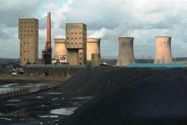
Agecroft Colliery 1988
Copyright © Frazerweb and used with permission
Sinking here seems to have commenced in the 1840s, although several different dates have been given by various sources. Two shafts were sunk, 22 yards apart and 9ft 6in diameter, one being the downcast shaft and the other an upcast furnace shaft. A depth of 580 yards to the Dow (Doe) Mine was reached and when in full production 650 tons were being raised each day. A large amount of water was encountered during the early stages of the sinking and from approximately 16 yards from the surface it was necessary to insert cast iron tubbing for the next 150 yards. Brick walling sufficed for the remainder of the sinking but the shafts were not completed until 1856.
A 40in x 54in single cylinder vertical winding engine was erected by J. Musgrave of Bolton in 1855. It was fitted with a cast iron flywheel 12 feet diameter and two 10 feet diameter reels for flat ropes. The timber head-gear was arranged back to back with the engine house with a single pulley over each shaft. Except for the substitution of round ropes for the original flat ropes, this winding arrangement continued until the shafts were abandoned in 1930.
In the early 1890s steam was supplied to this engine by a range of eight Lancashire boilers 7ft 6in x 30ft, working at 70psi. Steam was also taken down one of the shafts in two 6in diameter pipes to supply underground haulage engines and pumps. The boiler plant was renewed in 1895 when five 8ft x 30ft Lancashire boilers working at 80psi and made by Yates & Thom of Blackburn were installed.
Underground pumping plant and water lodges were placed near to the downcast shaft at 160 yards, 360 yards and 580 yards (pit bottom) from the surface. At each station the pumping plant comprised a twin-cylinder horizontal rotative engine with two double acting rams and a twin-cylinder horizontal direct acting pump with four single acting rams. The rotative engines were made by Slee & Co., Earlstown and the duplex pumps by Messrs Fielding & Platt, Gloucester.
Ventilation was improved in 1892 by the installation of a fan built by Walker Bros., Wigan. This was 14ft diameter by 5ft wide and could circulate 60,000cfm at 2.4 inch water gauge, when running at 154rpm. The driving engine was a 16in x 36in single cylinder horizontal running at 58rpm and fitted with a condenser. The flywheel was 16ft diameter with six ropes coupled to a six foot diameter fan pulley.
Two new shafts were commenced about 1894, the intention being to reach the Trencherbone Mine at approximately 700 yards from the surface. The shafts were numbered 3 and 4 the latter was the upcast shaft and the diameters were 14ft and 15ft respectively. During the sinking of No.3 shaft a belt of quicksand was struck just below the surface and two rows of piling were driven to hold this in check. As the sinking progressed considerable makes of water were encountered requiring pumping up to 350 gallons per minute. Cast iron tubbing was inserted in this section of the shaft. By contrast No.4 shaft was relatively dry and only a small amount of pumping was needed. Steam for the sinking engines, sinking pumps, and temporary fan was supplied from the five Yates & Thom boilers.
The permanent winders installed at the new shafts were both second-hand engines. The No.3 Pit engine was a twin cylinder horizontal 36in x 72in with Cornish valves and a 22ft diameter drum. It was built by Robert Daglish of St Helens and was obtained from Rosebridge Colliery near Wigan. The No.4 Pit engine was a twin cylinder vertical 32in x 72in from one of Andrew Knowles’ collieries at Radcliffe, either Within’s Lane or Allen’s Green. It was built by J. Musgrave in 1877 or 1879 depending on which colliery it came from. The cylinders were fitted with Cornish valves and the winding drum was 20ft diameter.
To serve the winding engines at the new shafts and other permanent steam driven plant a total of 13 Lancashire boilers were installed working at 80/100psi. It would appear that some at least of these boilers were second-hand as the sizes were not uniform.
In 1899, Walker Bros. supplied an 18in x 36in fan engine with two cranks to duplicate the engine, 16in x 30in single cylinder, which had been supplied in 1892. It would appear that rebuilt as a twin cross-coupled engine one side had a larger cylinder than the other. Although Walker Bros. records are not specific, they probably supplied a cross-compound two-stage air compressor to the new section of the colliery, always known as ‘The New Winnings’, in 1899/1900. This engine delivered air at 65psi and had air cylinders 28in and 42in bore and 48in stroke. The steam cylinders were 24in + 42in x 48in and were fitted with Meyer slide valves. At the same time, Walker Bros. took down one side of a duplex air pump fitted to an air compressor at Pendleton Colliery and re-erected it at Agecroft. In 1910, Walker Bros. supplied a cross-compound two-stage air compressor to which specific mention is made as being destined for Agecroft. As ordered the air cylinders were 31in and 51in diameter and the steam cylinders 32in + 58in x 60in stroke. The flywheel was 22 tons in weight. There seems to have been a change of mind as a note states ‘Steam 26 & 51 inches, Air 27 & 47 inches’. These would appear to be the air cylinders retro-fitted to the duplex compressor at Wheatsheaf Colliery following the closure of Agecroft. All the engines exhausted to condensers for which a timber cooling tower was built. The owners were obviously proud of their fan engine which was named ‘Pride of Agecroft’.
At the time of opening of the New Winnings a new coal screening plant was erected and the railway sidings considerably extended. Outlets for coal were to the former Lancashire & Yorkshire Railway and the Manchester, Bolton & Bury Canal. The canal was served by a tub tramway with endless chain haulage which crossed over the L&YR before reaching a timber pier with tippler alongside the canal.
By the late 1920s the surface plant was in poor condition and if local accounts are to be believed underground development work had not been kept ahead of current workings. The old 1 & 2 shafts were abandoned and filled in, at least for a short time. One morning when the workmen arrived the shafts had reappeared the filling having been washed away by subterranean water. Further filling had to be carried out to make the job permanent.
The New Winnings did not last much longer as they were closed down in 1932. Demolition of the surface plant took place in the mid-1930s but the shafts were not filled up. They were ringed with brickwork and a small pulley erected over each. The chimney was left standing.
In the years following Nationalisation and following successful trial borings in the hitherto unworked area around Prestwich and Whitefield it was decided to tap these reserves which lay on the east side of the Irwell Valley Fault. It was deemed feasible to use the Agecroft Colliery site for a new colliery to work these reserves which would involve tunnelling through the Fault. The Nos.3 & 4 shafts were of suitable size for future use and there was to be a new shaft 24 feet diameter in addition.
Six second-hand Lancashire boilers were installed about 1953 to supply temporary and second-hand steam winding engines installed at Nos.3 & 4 Pits. At the No.5 Pit sinking temporary electric winders were installed. The opening up of the old shafts presented some problems. The brickwork linings had deteriorated and due to the economic conditions prevailing when the old colliery was demolished, shaft equipment which had no value had been cut off at the surface and allowed to fall down. In addition the shafts had formed a convenient repository for the local residents’ rubbish.
No.4 shaft, 672 yards deep, was in the worst condition and it was decided to fill it up with ashes and start again as for a new sinking, dealing with the miscellaneous debris as it appeared. The lining was renewed in reinforced concrete. Where caving had occurred in the shaft wall, the cavities were filled with a cement-ash mixture. No.3 shaft, 674 yards deep, was in better condition although out of vertical line. The cast iron tubbing through the water bearing strata was able to be reconditioned in situ. Below 300 yards depth, a new concrete lining was formed down to the shaft bottom. The new shaft, No.5, sunk to 668 yards, was lined in concrete throughout and water encountered during the sinking was held back by cementation of the strata.
During development, No.3 shaft was used as the main winding shaft and the temporary winding engine here was a twin-cylinder horizontal, 30in x 72in made by John Wood & Sons, Wigan, in 1908, Nos.158112. It had been built for Ackers, Whitley & Co., Bickershaw Colliery, and was reconditioned by the makers for Agecroft in 1953. The engine wound a single cage and counter-weight. At No.4 shaft, the temporary winding engine was again a twin-cylinder horizontal, but smaller than the No.3 engine and fitted with slide valves.
Tower mounted permanent winding engines were installed at Nos.4 and 5 shafts, these being of the 4-rope friction wheel type. The former shaft was to be the coal winding shaft and was fitted out with a 15-ton capacity skip and counterweight. No.5 shaft was intended for men, materials and stowing dirt and was equipped with a four-deck cage and counterweight. Two balance ropes were fitted under the cage and counterweight. At both shafts, the winding engines were powered by 2,500 horse power direct current motors running at 530rpm and taking power at 800 volts. Power was supplied from mercury arc converters.
No.3 shaft was provided with a ground mounted electric winding engine and a two deck cage and counterweight. This shaft and No.4 were linked to form the upcast ventilation shafts, No.5 being the downcast shaft.
Underground, two horizon tunnels were driven through the Irwell Valley Fault, No.1 at 324 yards, and No.2 at 485 yards from the surface, the latter being the main haulage tunnel, with diesel locomotives and three ton capacity mine cars. During development, driveages were also made in the opposite direction to the main tunnels. These secondary driveages were to intersect the Worsley Four Foot Mine, by which means early production could be obtained to offset the cost of the main development. With the presence of the Irwell Valley Fault and the working of the wet Worsley Four Foot, the colliery soon gained a reputation for wet conditions. Although the general dip of the strata was around 1 in 3, the drag of the Irwell Valley Fault caused local increases in the dip and inclinations of 1 in 1.8 were encountered.
As the workings were to be beneath an intensely built-up urban area and one of high property values, pneumatic solid stowing of the wastes was designed into the method of working. This necessitated the importing of ‘dirt’, which was taken down No.5 shaft and transported along No.1 horizon tunnel. To meet the high compressed air requirement, two Fraser & Chalmers 10,000cfm turbo-compressors were installed plus a Belliss & Morcom 3,000cfm reciprocating compressor.
The colliery was designed for an output of one million tons per annum, with small coal of under half inch size going to the nearby Agecroft Power Station to which a belt conveyor was constructed. Development costs meant that it would take an estimated 100 years production, the projected life of the colliery, in order to break even financially. In the event the colliery closed in July 1990 and the two winding towers were blasted down in January 1992. This marked the end of mining in the Manchester coalfields.
AGECROFT COLLIERY – No. 3 Pit
| Ft | Ins | |
|---|---|---|
| Bassy Coal | 741 | 0 |
| Bin Mine | 931 | 4 |
| Shuttle & Crumbouke Mine | 1031 | 3 |
| Rams Mine | 1161 | 5 |
| Dow Mine (Doe Mine) | 1798 | 0 |
| Five Quarters | 1834 | 5 |
| Victoria Mine | 1960 | 1¼ |
| Trencherbone Mine | 2119 | 3 |
| Coal | 2161 | 6 |
| Shaft Bottom | 2162 | 6 |
Further information:
- Bernard Platt’s Lancashire Collieries website
- John Beswick was a miner at Agecroft Colliery. Listen to this emotive account of his experiences at Agecroft.