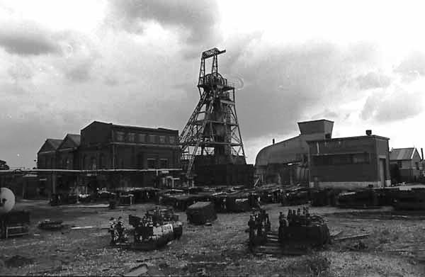
Golbourne Colliery
The colliery was first sunk in the 1860s and was served by two shafts, the No.2 Upcast and the No.3 Downcast. No.2 was 4.2 meters in diameter sunk to 545 meters and was used for manriding. The No.3 shaft was 5.4 meters in diameter sunk to the same depth and was used for men and materials.
In August 1975 an underground connection to the Bickershaw Colliery was made and in April 1977 all coal winding operations at the Golborne Colliery were stopped and the coal was wound at Bickershaw. Parsonage Colliery in Leigh was also connected to the Bickershaw Colliery.
By the late 1970s, the Golborne Colliery was one of twenty-two producing coal in the NCB Western area. The colliery employed 870 men, 766 of whom worked underground and 104 on the surface and produced 9000 tonnes of saleable coal per week from four seams. These were the Crombuke, the Ince Six Feet, the Higher Florida and the Plodder seams.
An explosion of firedamp occurred in the Plodder Seam at the colliery on the 18th March 1979, when ten men died and one was seriously injured. A report on the disaster can be found here.
A BRIEF HISTORY OF GOLBORNE COLLIERY – NCB Booklet 1960s
No.1 Shaft is 14 ft in diameter and was sunk in 1880 to the Lower Florida Seam at a depth of 150 yards. When the coal was worked out it was filled in 1943.
No 2 Shaft is the main upcast ventilation shaft and is 14ft in diameter. It was sunk to the Florida at a depth of 150 yards in 1880 and was deepened to 280 yards in 1890 to the Wigan seams and again in 1902 to a point 80 yards below the Arley seam, a total depth of 600 yards. It is used for manriding and materials.
No 3 shaft is the downcast ventilation and coal winding shaft. It is 18ft in diameter and was sunk to a depth of 600 yd in 1902. It is also used for winding materials and men. The colliery was acquired by Richard Evans and Co in 1880 from the previous owner Mr Edward Johnson. At this time the Nos. 1 and 2 shafts were down to the Florida seams. Working commenced on these in 1883 and continued until their exhaustion in 1943.
The colliery has worked almost continually since 1883 except for two periods 1932 and 1936 when it closed down due to trade depression.
During the early years of the life of the colliery, the seams were won by dip haulage roads from the shafts but at a later date after the sinking of the No 3 shaft, a level tunnel was driven out at a depth of 590 yds from the surface to intersect all seams from the Arley to the Higher Florida. The present colliery is divided into two parts by an east/west fault which has a downthrow 180 feet north. the northern area has been extensively worked in the past and at present no coal is being worked in this area.
A conservative estimate of the reserves available at the colliery is 29,000,000 tons giving a life of over seventy years at the planned output of 1,650 tons per day.
In 1949 two level tunnels were driven to investigate the south area. these tunnels reached the Wigan Four feet seam and in doing so proved the Peacock and the Trencherbone seams. Development in the Wigan Four Foot seam, for some 1200 yd across the take, proved the area to be promising and the Trencherbone and lower Florida seams are now being worked. the tunnels have now been extended to the Crombuke seam.
To enable the colliery to build up it6s output and to exploit the south area to the best advantage, a reorganisation scheme has been carried out. The scheme included for the introduction of a diesel haulage locomotive, the reorganisation of the pit bottom to reduce manpower, the electrification of the surface winders, the erection of pit head baths and the provision of adequate ventilation and compressed air.
SHAFTS AND WINDING
a) No.2 Shaft.
The original steam-driven winding engine was manufactured by John Woods and Sons in 1896 and had two cylinders 30 inches in diameter, with a 60 inch stroke. This has now been replaced by a new winding engine manufactured by Metro-Vicks/John Wood and installed in July 1956. It is a single cylindrical drum type, having a diameter of 15 ft and a drum width of 8 ft. The drum is driven through a double reduction gearing, ratio 34 to 1, from a 2.2k.v. slip ring induction motor of 200 hp at 575 rpm.
b) No 3 Shaft.
The original winder was built in 1907 by Fraser Chalmers and consisted of a pair of compound engines with cylinders 28 inches and 46 inches in diameter, with a 60 inch stroke.
The engines were very lightly built and had been in operation for fifty years and owing to the threatened closure of the colliery on two occasions, had not been adequately maintained. this winder was replaced in July 1956 by a new electric winder manufactured by Metro Vicks/Vickers Armstrong and is a a double compartment single cylindrical drum type, having a diameter of 16 feet and an overall drum width of 8 ft. It is driven through a single reduction gearing from an 11kv slip ring induction motor of 1400 hp at 356 rpm.
COAL HANDLING ARRANGEMENTS
a). Surface.
On the surface, pneumatic decking rams are used to load and unload the cages at No 3 shaft top and the tubs are controlled by associated retarders and stops.
b). Underground.
Prior to 1951, simultaneous decking was in operation at No 3 shaft. the pit bottom had now been completely reorganised with fully automatic control of full and empty tubs.
The full tubs are left by the locomotive about 100 yards from the shaft and gravitate to the cages. They are controlled by retarders until they reach the uncoupling station, from which point they gravitate to the decking plant adjacent to the shaft. From here they are under the control of the onsetter, who operates the automatic rams, tilting platforms and other cage gear.
The empties gravitate from the shaft on a series of creepers which move the tubs forward for assembly in readiness for the locomotives which operate in the main transport system. The locomotive haulage system is handled by 70 hp diesel locomotives.
COAL PREPARATION
- The run-of-mine coal is tippled on either of two classifying screens and classified into large +6″,
- Cobbles 6″ x 3″ and -3″.
- The +6″ passes along a picking belt and is cleaned by hand.
- The 6″ x 3″ size is cleaned mechanically by a Greaves wash-box.
- The -3″ is conveyed to a surge bunker and is fed out at a constant rate and delivered to a high-speed screen.
This high-speed screen gives two products, 3″ x Å” which is sent away for washing and Å” x 0″ which is sold untreated.
VENTILATION
Ventilation is provided by a Walker Indestructible Fan installed in 1908. the fan is 20 ft in diameter and 7′ 6″ wide and was designed for a duty of 350,000 cfm at 4″ water gauge running at 129 rpm.
The original steam drive was by half compound engine developing 176 bhp but this was replaced in 1955 by an electric drive housing a 300 hp AC synchronous motor running at 300 rpm.
In order to meet future requirements, a new exhausting single inlet radial flow fan of the backward aero-foil bladed type has been erected on the surface in a new fan house. The fan is capable of passing 360,00 cfm at 10.5″ water gauge; it is driven by a 800 hp synchronous induction motor through a three speed gearbox to give the flexibility of performance
POWER SUPPLY
a). Steam.
The original steam raising plant consisted of a battery of six Lancashire Boilers, five of which were normally in steam and one kept as spare. they were installed in 1906 and were in very poor condition. With the electrification of the surface plane, it had been necessary to keep only two boilers, one as stand bye to provide low-pressure steam for space heating and the surface buildings.
b) Compressed air.
There are two main units at the colliery, both by Bellis & Morcom, two-stage double crank vertical reciprocating air compressors each with a capacity of 2100 cfm. Both are electrically driven by 400 hp 2200 v motors.
There is an 8″ diameter compressed air range in the No 2 shaft and the districts are supplied by 6″, 4″ and 3″ ranges.
This capacity was not adequate for the future needs of the colliery and the supply had been augmented by a 1,100 hp electrically driven set with a capacity of 5250 cfm. This additional compressor is housed in an extension to the existing compressor house.
c) Electricity.
Electricity is obtained from the North Western Electricity board at 11.000 volts transformed doom to 2200 volts by means of 3x 1500 KVA transformers.
The electricity supply underground is at 2200 volts and is supplied by shaft cables down No 3 shaft.
OTHER SURFACE BUILDINGS
a) Baths
A new pithead baths has been erected having accommodation for 1092 workmen and 12 officials. The building incorporates a canteen, medical centre, and par offices.
b). Lamproom.
The lamproom has a capacity for 1100 lamps.
c). Stores.
These are housed in a new stores building and materials stockyard
MINING CONDITIONS
The measures in the Golborne Colliery take an average gradient of 1 in 4 in the southeasterly direction. The area also has a considerable amount of minor faulting, especially in the northern area.
In the southern area, a high gas yield had been encountered and methane drainage is practised to provide safer working conditions.
OUTPUT
After reorganisation and up to 1960 an output of 1500 tons per day on two shifts was obtained from the Crombuke seam in the Northern area and the Trencherbone in the Southern area.
Consequent to the exhaustion of the Crombuke seam in the north area, the output has been obtained in the South area of the Lower Florida and Trencherbone seams. In June 1961 three shift winding was introduced resulting in an increase in the average output up to 2250 tons per day. Coal is produced from four faces working double shaft on a shift rotation basis, giving colliery output on three shifts.
Power loading using the Anderton Shearer Loaders in conjunction with flexible armoured conveyors is employed on all faces and on the Trencherbone rise face Gullick “Seamer” 5-leg self-advancing powered supports are also in operation.
NCB BOOKLET 1960s
The plans below have been prepared by Lee Reynolds and used here with his permission.
Composite plan of all seams
Crombouke Seam
Higher Florida Seam
Lower Florida Seam
Ince 6ft Seam
Peacock Seam
Plodder Seam
Trencherbone Seam
Return to previous page