DONISTHORPE COLLIERY (SK 312143)
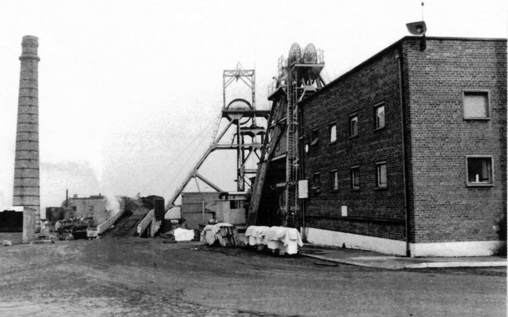
General view of colliery surface showing the chimney and No.1 Pit headgear.
On the right is No.2 Pit engine house. Geoff Hayes 1977
Sinking at Donisthorpe was commenced in March 1871 by the father and son partnership of G. Checkland and G.E. Checkland. Two shafts were sunk, each 14 feet in diameter to the Main Coal seam at approximately 223 yards from the surface and intersecting the Little Coal seam at approximately 159 yards. The Main seam was 14ft. 6in. thick at this location. Large areas of coal were purchased or leased, the areas including Donisthorpe itself, Overseal, Netherseal, Stretton-en-le-Field and Clifton Campville.
The large financial outlay involved in the Donisthorpe undertaking put the Checklands heavily in debt. Faulting of the strata, steep dip in places of the seams and inundation were further problems, together with prosecutions by the Inspector of Mines. A limited company was formed in 1886 and this company deepened the shafts to 288 yards to reach the Stockings seam at 257 yards in 1890. This did not overcome the difficulties and the colliery was sold in March 1903 to a new Donisthorpe Company which put the concern under the control of the Moira Colliery Co. Ltd. This company were the major colliery owners in the Western Basin of the Leicestershire coalfields. They were also the major colliery owners in the South Derbyshire coalfield, of which the Western Basin coalfield was an extension.
The area of the take was now about two miles from north to south and approximately two and a half miles generally from east to west. On the eastern side, the workings were bounded by the Boothorpe Fault, to the south-west the seams outcropped and the western boundary was defined by major faulting. Seam dips were not excessive except in the vicinity of major faults and near the outcrops where strata “drag” could cause inclinations of 1 in 1½.
Shafts – The two shafts were not sunk any further than the deepenings of 1890, i.e. the Stockings seam at 257 yards. No.1 Shaft was the downcast and coal winding shaft and No.2 shaft, was the upcast ventilation shaft for the colliery.
The original headgears were of timber and the No.1 shaft cage guides were of pitch pine. No.1 headgear was replaced in 1951 by a steel structure from the closed Netherseal Colliery. No.2 shaft also received a new steel headgear.
 Winding – At No.1 shaft a twin-cylinder horizontal winding engine was installed by a now unknown builder. The engine was subsequently rebuilt with 26in. x 54in. piston valve cylinders, the piston valves being plain without any means of varying the cut-off. Gooch valve gear was fitted for reversing. The winding drum was parallel, 13 feet in diameter with a brake path on each side, acted upon by straight post brakes. Locked coil winding ropes, one and five-sixteenths inches diameter were provided. Overwind and overspeed protection was by a Melling’s (Worsley Mesnes) pneumatic controller. Apart from the piston valves, the engine was typical 19th century with a flat bedplate and four-bar crosshead guides. Not long before the engine ceased work, the bedplate fractured and was repaired by metal stitching.
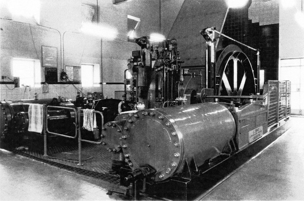
Amongst improvements carried out by the National Coal Board was the replacement in 1952 of 15 cwt capacity tubs by 3¼ ton capacity mine cars. The winding arrangements were altered so that a single minecar was wound in each cage. This resulted in improved winding times and the winding engine could perform 100 winds per hour from 257 yards. There was plenty of exhaust steam available and this was piped to a boiler feed water heater converted from an old Lancashire boiler. Other improvements by the National Coal Board included a new engine house built in the architectural style of the time, complete with a flat roof.
The engine was replaced in 1977 by an electric winder from another colliery. This could not better the winding rate achieved by the steam winding engine, 90 winds per hour being the maximum obtained.
No.1 Shaft pit top arrangements – Colliery Engineering
No.2 Pit winding engine was a twin-cylinder horizontal and carried a plate denoting that it had been built by J. Jessup, London Boiler & Steam Crane Works, Leicester, although no date was specified. Originally built with slide valve cylinders, Worsley Mesnes Ironworks rebuilt the engine with new piston valve cylinders in 1916. Worsley Mesnes also put forward a proposal to prevent the engine bedplate from moving on its foundations. This does not appear to have been proceeded with and information is lacking on how this problem was resolved.
The colliery company suggested at this time that the steam pressure might be increased to 100 psi., but Worsley Mesnes considered that the engine bedplate was none too strong as it was and that the working pressure should be restricted to 80 psi. So it remained until the end of the engine’s working life.
As rebuilt the engine had 24in. x 48in. cylinders fitted with plain piston valves without any means of varying the cut-off. The piston valves were actuated by Stephenson’s link motion. Structurally the engine had the traditional flat bedplate, which Worsley Mesnes had remarked upon as not being very strong, and four-bar crosshead guides. On the crankshaft was mounted a 12 feet diameter parallel winding drum carrying 1¼ inch diameter locked coil winding ropes. Straight post brakes acted upon brake paths on each side of the winding drum. The brakes were operated by a Melling’s (Worsley Mesnes) brake engine. Overwind/overspeed control was by a Melling’s Patent pneumatic controller.
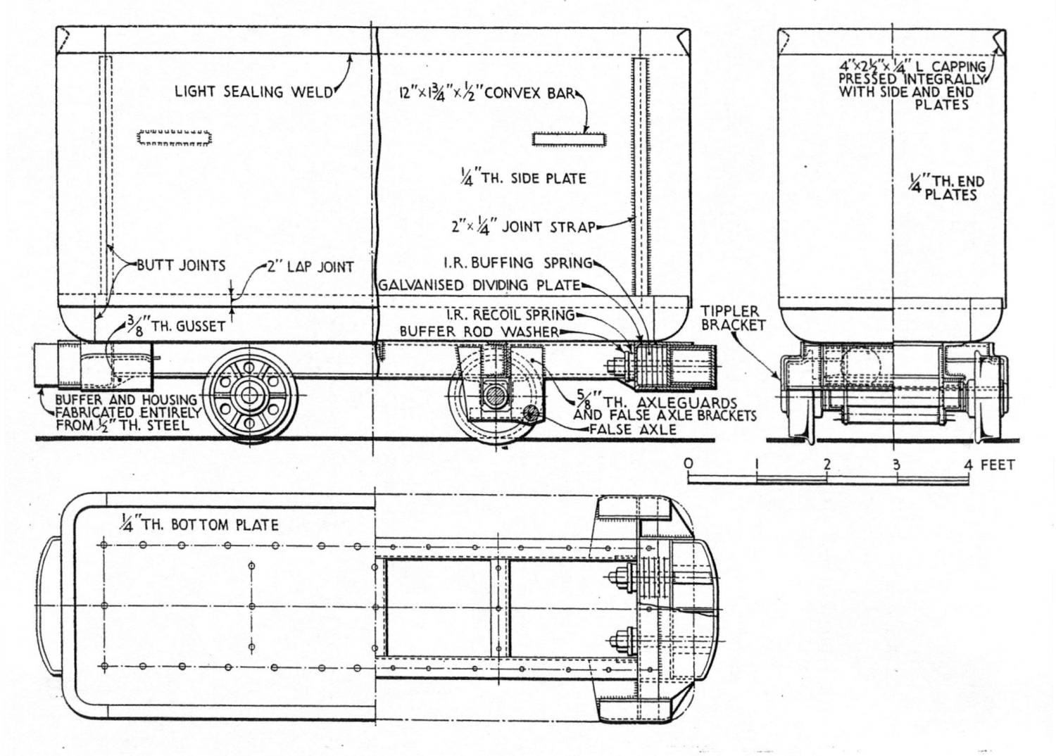
3¼ ton capacity mine car made by the Butterley Company for Donisthorpe Colliery – Colliery Engineering, 1953
Under National Coal Board management a very modern style engine house was erected around the engine, built-in brick and having a flat concrete slab roof.
No.2 Pit retained its steam winding engine until the closure of the colliery on 30 March 1990. Although the National Coal Board had enthusiastically gone in for electric winding, there was a long tail of steam survivors.
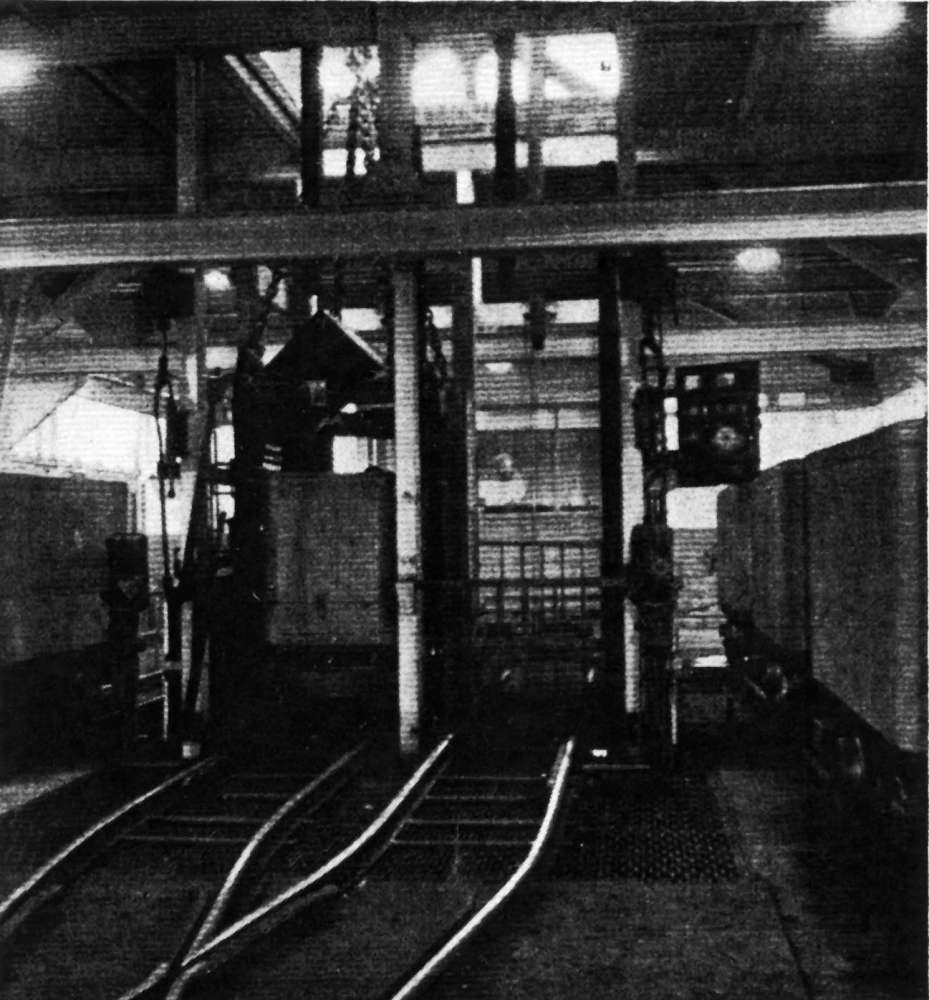
In 1952 a major improvement to the winding arrangements at No.1 Pit was completed. Coal was wound in 3¼ ton capacity mine cars made by Butterley and the mine car handling system was fully automated. The mine cars ran on 2ft. 6in. gauge tracks replacing 2ft. gauge 15 cwt capacity tubs. The mechanical plant of the new scheme was made by W.H. Barker & Son (Engineers) Ltd, whilst the pneumatic equipment and electrical controls were made by the Westinghouse Brake & Signal Co. Ltd.
Changing of the mine cars in the cages at the pit top and bottom and placing mine cars in the tipplers at the surface was carried out by pneumatic rams engaging with a dummy rigid axle under the mine cars. No locomotives were employed and movement around the mine car circuit at pit top and bottom relied on gravity. Around the pit bottom mine car circuit the necessary elevation for gravity working was obtained by “creepers” between the rails. Lugs on the creeper chain engaged with the dummy axle under the mine cars.
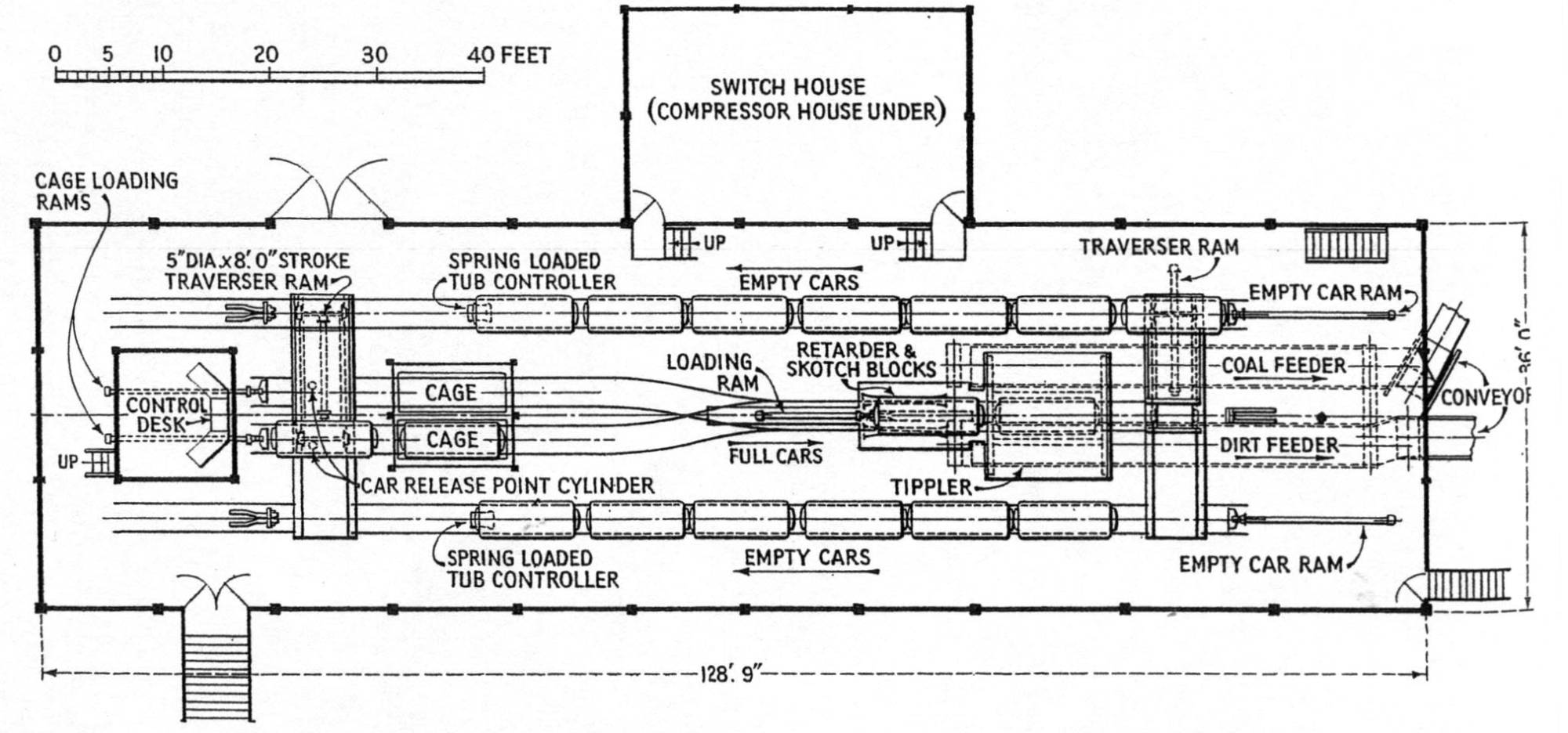
The layout of pit top mine car hall, Donisthorpe Colliery – Colliery Engineering 1953
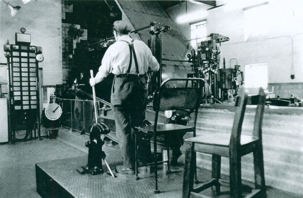
The mine car handling systems at pit top and bottom were operated by one banksman at the pit top and one onsetter at the pit bottom. The control desk at each location was located in a control cabin. Boilers – Steam was provided by five Lancashire boilers working at 80 psi., and fitted with superheaters. In later years the boilers were fired by Danks’s chain grate mechanical stokers in conjunction with Danks’s automatic ash extractors. The forced draught was provided under the grates and there was an induced draught fan in the main flue to the chimney. The chimney was a circular section constructed in brick.
Boiler feedwater was drawn from the feedwater heater. Three Weir SIMPLEX vertical steam pumps were installed together with a standby electrically driven turbine pump. There was also a live steam injector which was supplied with cold water.
Ventilation – In the earlier years of the colliery a Waddle Patent fan was provided and this may have been the initial means of ventilation at the colliery. By 1914, this fan had been replaced by a SIROCCO fan.
Pumping – A steam-powered pumping engine was initially provided. This had been replaced by an electrically driven pump by 1914.
Compressed Air – The compressed air required for the mine car handling systems at pit top and bottom was supplied at 60 psi by Westinghouse C.M.38 compressors. This type of compressor had originally been developed for use on the braking systems of electric railway rolling stock. The compressors were twin-cylinder single-acting self-cooled type which in colliery service were direct coupled to 10 horsepower AC squirrel-cage induction motors.
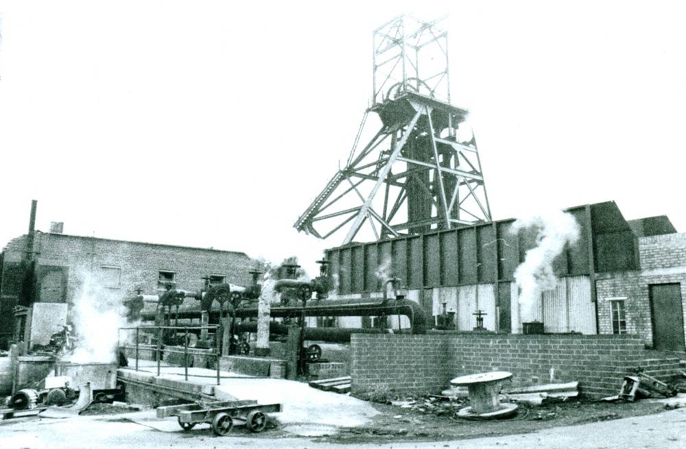
No.1 Pit headgear, engine house (left) and tops of boilers with main steam pipework. Geoff Hayes 1977
Six compressors were installed for the pit top equipment and three units for the pit bottom system. To supply the requirements of the pit top equipment, five compressors were adequate leaving the sixth unit as standby. To even out demand variations the compressors fed into a range of four 22 cu. ft. air receivers made by Messrs, Farrer of Newark-on-Trent.
Underground Transport – Transport of coal underground was entirely by conveyor belts by the early 1950s. Coal was fed by the conveyor system to a central loading point near the pit bottom where the coal was transferred to the mine cars for winding. The trunk conveyor was driven by a 140 horsepower motor taking alternating current at 3300 volts. The drive to the conveyor was transmitted by a Vulcan-Sinclair fluid coupling which allowed the motor to run up to 75% speed before picking up the load. Sequence controls were fitted throughout the system to ensure that the various feeder conveyors did not start until the main conveyor was running and vice-versa.
Materials were transported along the man-riding roadways from and to the No.2 shaft. Motive power was a 68HP Hunslet diesel locomotive.
Underground Working – As was usual in the coalfield, the Main Seam was extensively worked over the large area of “take” available to the colliery. Little knowledge is available of the early working of the colliery but it would appear that both longwall and possibly pillar and stall working was employed.
By the early years of the National Coal Board, the Woodfield and Stockings seams were being worked again over a wide area. The Woodfield seam was intersected at 240 yards in No.1 shaft. The Stockings seam was 8 feet thick of which 7 feet was extracted and the Woodfield seam was 4ft. 6in. to 5 feet in thickness. When being worked 6 inches of coal was left up as roof in the Woodfield seam. Fairly numerous small faults were present throughout the area and the Stockings seam was liable to spontaneous combustion.
Due to the closeness of these two seams extraction of one seam affected working conditions in the other. Generally, intake haulage roadways were driven in the Stockings seam with the return air roadways in the Woodfield seam. Advancing longwall faces were extracted in the Woodfield seam. When the boundary was reached retreat working was immediately commenced in the Stockings seam beneath the extracted area.
By the 1970s, old goaf areas of the worked-out Main seam in the Oakthorpe area had been re-entered. This was to win the large quantities of slack and small coal which had been thrown into the wastes in the early years of working. The old goafs containing the small coal, by now well crushed, were worked longwall retreat. The recovered coal was sold as power station fuel.
A Joy Continuous Miner machine was tried at Donisthorpe for headings in coal. This machine was worked on the American system of mining with a shuttle car carrying coal from the coal getting machine to a loading point on a conveyor belt. The machine was only suitable for thick seams, a feature of Donisthorpe Colliery, and there was at least some degree of success. A major drawback was that large quantities of small coal and slack were produced and the experiment at Donisthorpe was later terminated.
Coal Preparation – Coal leaving the pit-top tippler was delivered onto an apron feeder which elevated the coal for some 6 feet and discharged onto a chute which in turn fed a troughed conveyor belt for transporting the coal to the screening plant. Incorporated into the conveyor belt was a Blake-Denison totaler weighing machine.
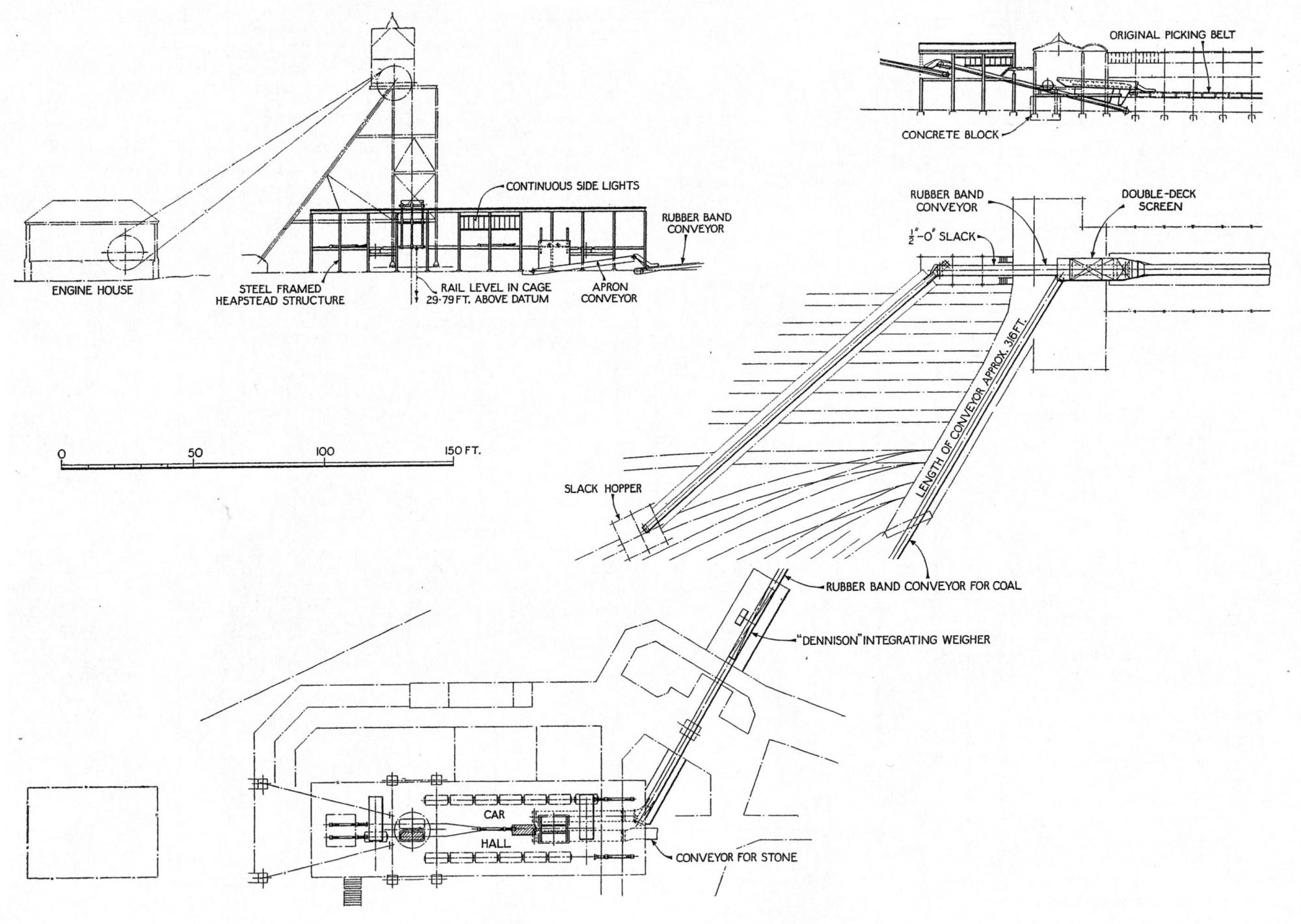
Elevation and plan of pit top conveying and decking arrangement at Donisthorpe – Colliery Engineering 1953
At the screening plant, the conveyor delivered the coal onto a double-deck shaker screen. Coal more than 2-inch size passed over the upper screen and onto a 54in. wide plate-type picking belt from which the best coal and dirt were picked by hand. Coal not lifted from the picking belt was screened into nuts (2in. to 3in.), small cobbles (3in. to 4in.) and large cobbles (4in. plus).
Coal falling through the upper screen fell onto the lower screen, which had ½ inch diameter holes. Coal less than ½ inch in size was delivered onto a conveyor belt by which it was transported to a 90 ton slack bunker. Coal passing over the lower deck screen was further classified by size and passed through two parallel dry cleaners. Leaving the dry cleaners the coal was delivered to overhead bunkers serving either railway wagons or road lorries.
Dirt wound from the pit was diverted on leaving the pit top tippler and transported by conveyor to an overhead bunker. This bunker discharged into 10-ton capacity side-tipping railway wagons for transit to the tipping site by shunting locomotive.
See Oakthorpe Colliery.
Copyright © NMRS Records: Geoff Hayes Collection
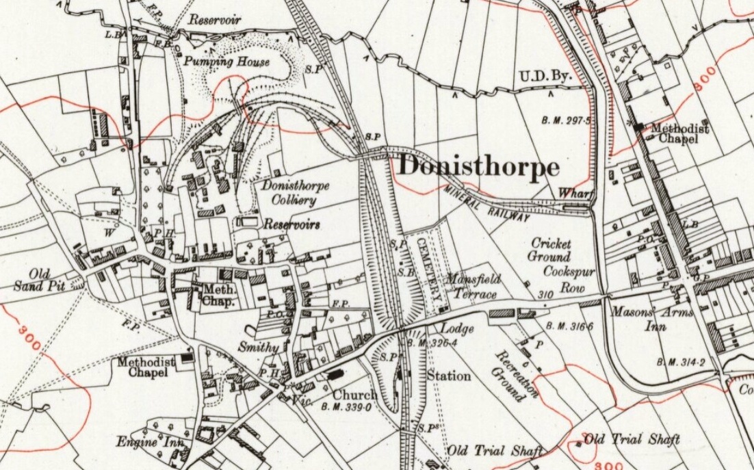
OS Map, Derbyshire LXIII.NE 1921
Reproduced by permission of the National Library of Scotland