| COLLIERY | GARSWOOD HALL | ||||||||
|---|---|---|---|---|---|---|---|---|---|
| LOCATION | Large area between LNWR St Helens – Wigan line and LNWR West Coast Main Line north of Golborne station. | ||||||||
| OWNERS |
|
||||||||
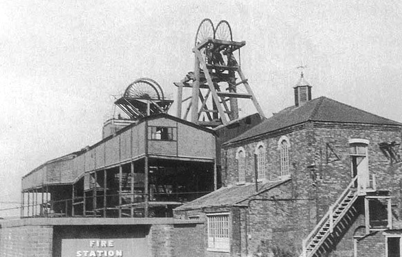
Garswood Hall Colliery
Shafts
- No.1 Pit, sunk c1867-68, 13 feet 6 inches diameter, 210 yards to Wigan Four Feet Mine, coal winding and downcast.
- No.2 Pit, sunk 1867-68, 13 feet 6 inches diameter, 445 yards to Arley Mine. Coal winding and upcast.
- No.3 Pit, commenced 1874, 15 feet 6 inches diameter, 445 yards to Arley Mine, Coal winding and downcast.
- No.4 Pit, commenced 1874, 12 feet diameter, 160 yards to Wigan Five Feet Mine. Coal winding and upcast (for No.1 Pit)
- No.5 Pit, commenced 13 April 1877, 15 feet diameter, 210 yards to Ince Seven Feet Mine. Coal winding and downcast.
- No.6 Pit, commenced c1877, 15 feet diameter, 350 yards to Pemberton Four Feet Mine. Later deepened to 700 yards. Coal winding and downcast, later became upcast.
- No.7 Pit, sunk c.1888, 18 feet diameter, sunk 350 yards to Pemberton Four Feet Mine, upcast only initially, later upcast and coal winding.
- No.9 Pit, commenced sinking 1 May 1901, sunk to 400 yards. Downcast and coal winding.
Winding
- No.1 Pit, twin cylinder horizontal engine, 16 inches x 36 inches, slide valves, “Diabolo” winding drum, 7 feet diameter (centre) to 9 feet diameter.
- No.2 Pit, twin cylinder horizontal engine by Baker & Valliant, Wigan, conical winding drum 14 feet to 16 feet diameter, cylinders 25 inches x 60 inches, slide valves.
- No.3 Pit, twin cylinder horizontal engine made at the colliery workshops, 28 inches x 60 inches, Cornish valves, parallel winding drum 17 feet 6 inches diameter, centre brake path.
- No.4 Pit, twin cylinder horizontal engine 16 inches x 42 inches, conical drum, 9 feet diameter.
- No.5 Pit, twin cylinder horizontal engine, Wood & Gee, 1887, 20 inches x 42 inches, slide valves, 10 feet diameter parallel drum, four tubs wound in double deck cages.
- No.6 Pit, twin cylinder horizontal engine made at the colliery workshops, 30 inches x 72 inches, slide valves, 10 inches steam reverser, winding drum parallel 21 feet diameter centre brake path. Four tubs wound in double deck cages.
- No.7 Pit, initially twin cylinder horizontal engine with 18 inches cylinders. 1895 – Twin cylinder horizontal engine, Walker Bros., 40 inches x 72 inches, Cornish valves, Musgrave (Steven’s) cut-off gear, winding drum 7 feet wide.
- No.9 Pit, twin cylinder horizontal engine.
NOTE – All winding ropes fitted with Ormerod detaching hooks.
Underground Haulage
- No.1 Pit (Wigan Five Feet), Twin cylinder horizontal engine at surface, 18 inches x 24 inches , geared 1 to 3 to second motion shaft carrying 5 feet diameter Clifton wheel. Engine adapted from old locomotive. Endless power rope down shaft operating an endless rope haulage.
- No.3 Pit, twin cylinder horizontal engine at surface, adapted from locomotive, 12 inches x 18 inches, geared to 5 feet diameter Clifton wheel, power rope down shaft operating two endless rope haulages in Wigan Nine Feet. Seam exhausted 1892 and engine adapted for hauling in King Mine. Twin cylinder, 15 inches compressed air engine in Arley Mine operating endless rope haulage.
- No.5 Pit, Engine at surface, twin cylinder 12 inches x 18 inches, rebuilt from old locomotive, geared to 5 feet diameter Clifton wheel. Endless power rope down shaft to vertical shaft in Ince Seven Feet Mine. Vertical shaft powered two haulages by Clifton wheels with friction clutches. One endless rope and one single direct rope.
Three steam operated engines located underground – Pemberton Five Feet, twin cylinder 6 inch engine operating direct single rope haulage.
Pemberton Four Feet – twin 6 inch engine operating direct single rope haulage.
Twin 10 inch engine geared to Clifton wheel operating endless rope haulage.
Steam supplied by underground boiler at No.7 Pit.
Ventilation
- No.2 (upcast) Pit, Walker “Indestructible” fan, 20 feet diameter. Duplicate engines with condenser, 24 inches x 48 inches, 16 feet diameter, flywheel, 10 – cotton ropes to 8 feet diameter fan pulley, engine 45rpm., fan 90rpm. 120,000cfm. in Nos. 2 & 3 Pits. No.4 (upcast) Pit (1892), Furnace producing approx. 50,000cfm.
- No.7 (upcast) pit (1892), Furnace approx. 250,000cfm. plus boiler. 1895 – Walker “Indestructible” fan 30 feet x 9 feet, cross-compound engine, horizontal, 26 inches + 48 inches x 60 inches, teak lagging, Meyer expansion slide valves on both cylinders, flywheel 24 feet diameter, 18 – 1¾ inches ropes to fan pulley. Steam 100psi.
- No.6 Pit (possibly), SIROCCO fan driven by Belliss & Morcom high speed enclosed engine, 570hp.
22-5-1946 (Pit not stated), Walker Bros., No.47947, MACARD axial flow fan, V-rope drive from motor, rated at 78,000cfm. at 5 inches water gauge. 895rpm., 79.8bhp.,77% efficiency.
Pumping
- No.4 Pit, single cylinder steam pumping engine at shaft bottom. 16 inches x 24 inches x 4 inches ram pumping to surface in 4 inch rising main.
- No.5 Pit, Main lodge room at 68 yards. Two horizontal pumps, 20 inches x 24 inches x 8 inches double acting ram, one duty, one standby. Operating 24 hours at 24rpm. Steam from surface boilers. Lodge room 102 yards below main lodge room, 15 inches x 20 inches x 4 inches, pump, pumping to main lodge. Compressed air operated.
- No.6 Pit, two compressed air pumps in dip workings of Pemberton Four Feet, pumping to shaft sump. Water pumped to surface by 24 inch steam pump with double acting plunger.
Compressed Air (1892)
- 25 inches steam, + 25 inches air x 56 inches stroke single air compressor. Standby compressor 16 inches + 16 inches x 36 inches (No.2 Pit) Nos.5 & 6 Pits, 20 inches + 20 inches x 36 inches compressor.
- 3-2-1898, Walker Bros. No.8135, cross-compound two-stage air compressor, 24 inches + 42 inches (steam), 24 inches + 38 inches (air) x 48 inches stroke. Corliss valves, flywheel 12 tons, steam 100psi., air 75psi.
- 6-6-1898 Walker Bros. No.8310, repeat order same specification as 8135, with governor.
- 15-9-1898 Walker Bros. No.8423, two air receivers 7 feet x 30 feet.
Electric Lighting (1892)
- Nos.1 – 4 Pits, DC generator by F.H. Royce, 1180rpm. Tangye inverted vertical compound engine 175rpm. 9 inches + 14 inches x 12 inches, leather link belt drive.
- Nos. 5-7 Pits, – Crompton DC generator, duplex inverted vertical engine 6 inches x 8 inches, 5 feet diameter flywheel, 9 inches pulley on generator, leather link belt drive.
Screening Plant
Nos.5 -7 Pits, Two single cylinder engines, one 16 inches x 24 inches, second engine 10 inches x 17 inches.
Workshops
Fitting shop and smithy, 15 inches engine and steam hammer.
Sawmill, 15 inches engine.
Boilers (1892)
Nos.1 – 4 Pits:
- 4 Lancashire boilers 7 feet x 24 feet.
- 1 Lancashire boiler 7 feet 6 inches x 30 feet.
- 1 Lancashire boiler 7 feet 6 inches x 26 feet.
- 1 Lancashire boiler 6 feet 6 inches x 25 feet.
Nos. 5 & 6 Pits – Six Lancashire boilers 8 feet x 30 feet fitted with three cross tubes in each furnace tube. 100psi. Made by Heaton & Son, Holt Town, Manchester.
No.7 Pit – One Lancashire boiler at pit bottom.
Seams Worked/Workforce (1954)
(Nos.5, 6, & 7 Pits.) Bulldog, Ravine, Orrell Yard (Haigh Yard), Arley. U/G 1104, S/F 209
CLOSURES
Garswood Coal & Iron Co. Ltd. taken over 6 May 1929. All GC & I Co. pits, except Long Lane, abandoned 30 June 1929.
Garswood Hall No.1 Pit 1905, No.4 Pit before 1930.
Long Lane No.2 Pit (ex. GC & I Co.) – March 1931.
Garswood Hall No.3 Pit, Temporarily closed 1931, subsequently re-opened.
Garswood Hall No.9 Pit abandoned November 1938.
Garswood Hall No.5 Pit pumping only by 1934.
Garswood Hall No.2 Pit ventilation only by 1934.
Long Lane No.1 Pit April 1955.
All remaining pits August 1958.
ACCIDENTS
- Explosion 2nd April 1902. During the sinking of No 9 pit a outburst of gas was ignited by a spark from a deliberately damaged cable. 8 died & 3 injured. The full report can be found here.
- Explosion 12th November 1932, No.9 Pit, Ravine Mine. 27 killed. Followed by two more explosions. The full report can be found here.
Copyright © NMRS Records: G. Hayes Collection
Return to previous page